Strategic Resource Intelligence

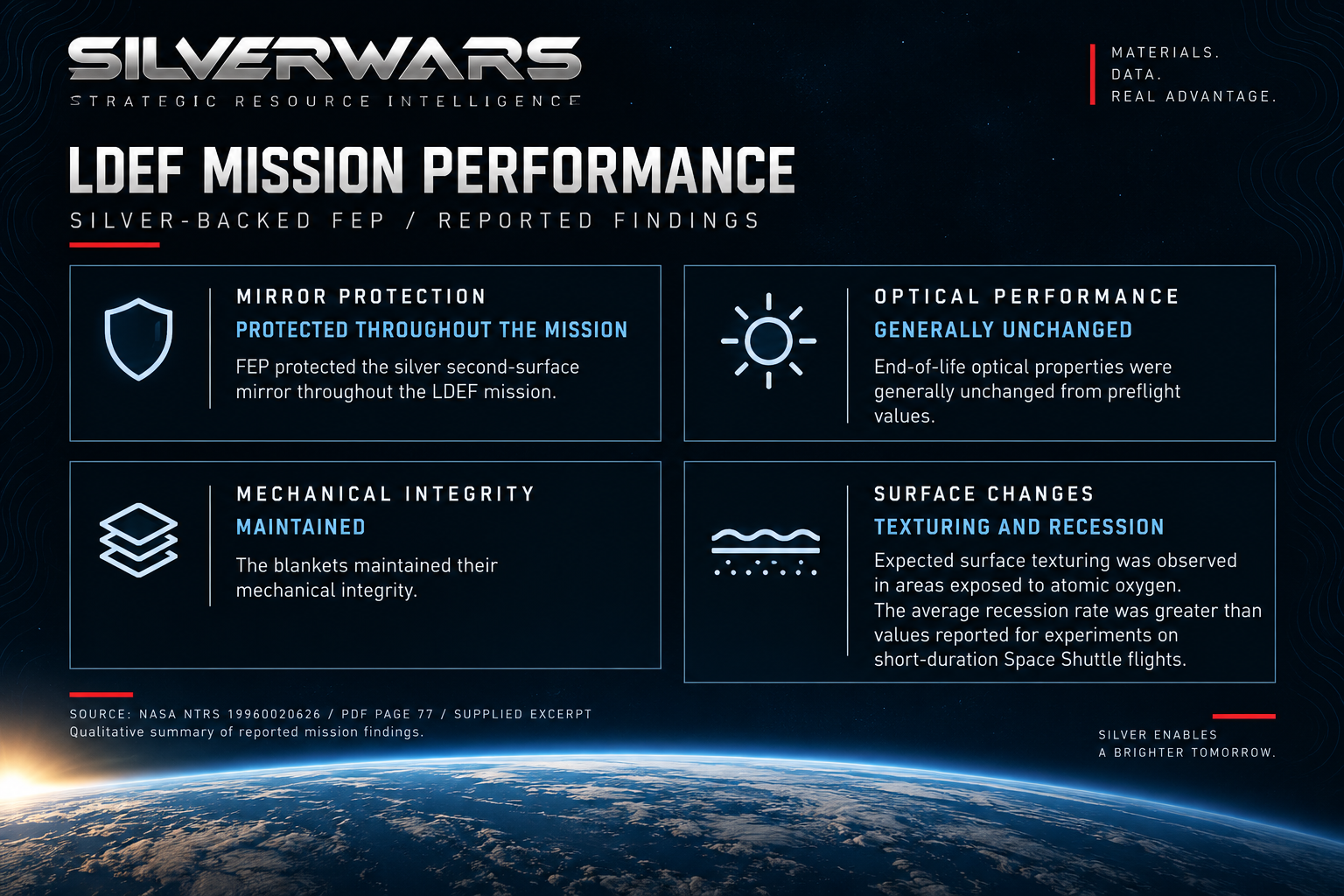
When NASA recovered the Long Duration Exposure Facility in January 1990, its silver-backed thermal blankets had spent 69 months in orbit. Tests of the returned material found that the blankets had generally preserved their optical performance. The polymer covering the silver had protected the mirror through a mission originally planned to last roughly a year.
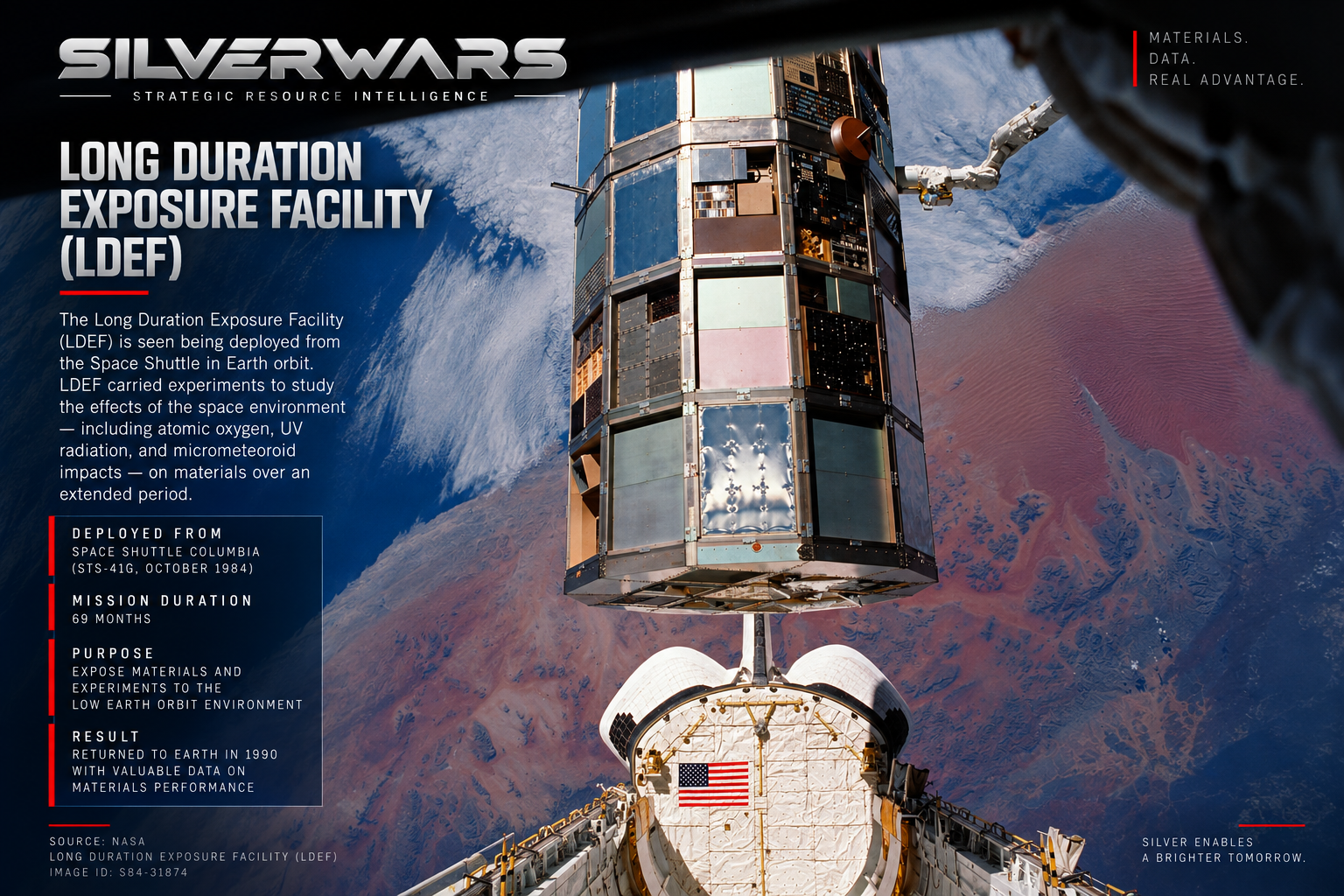
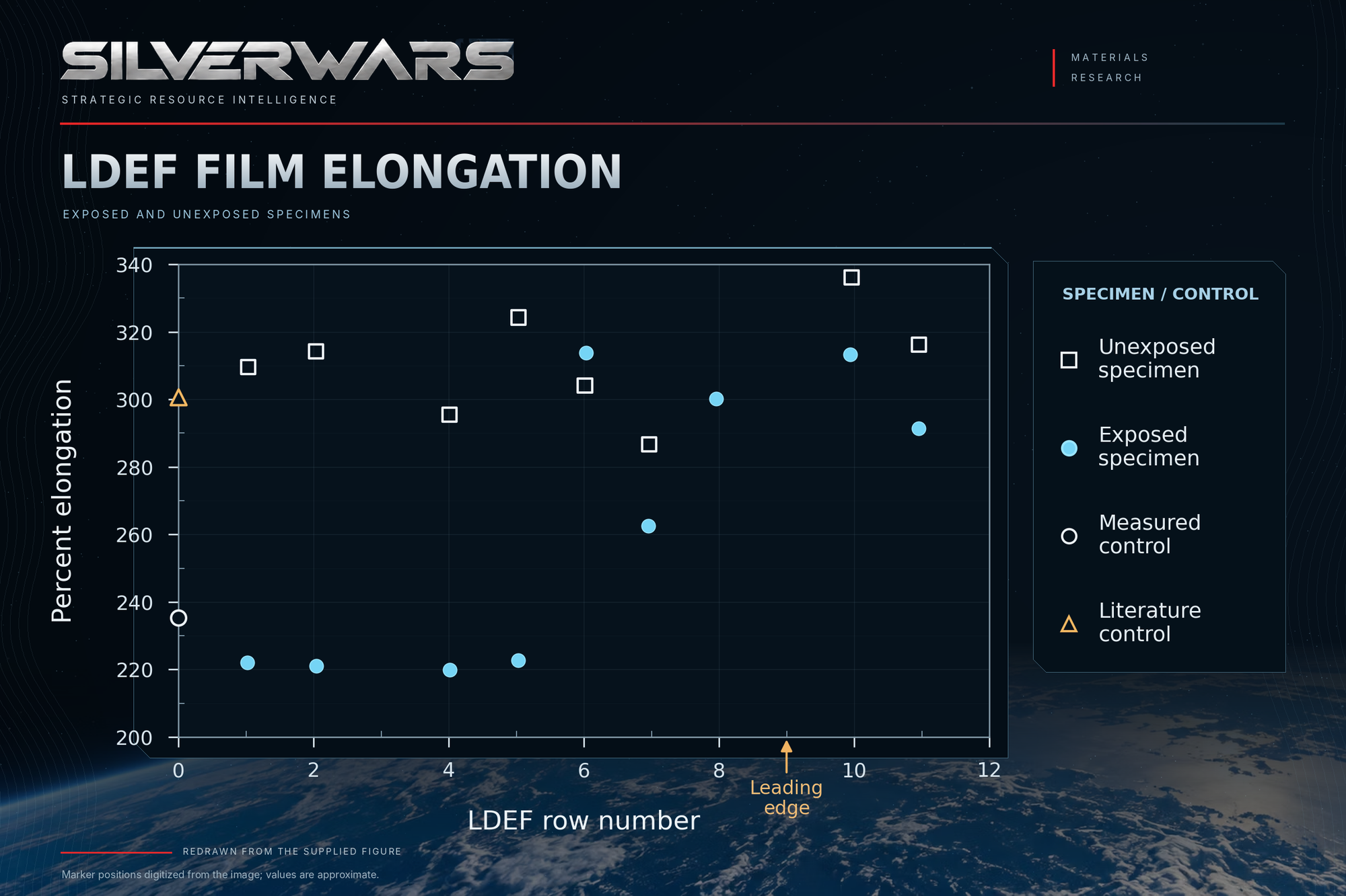
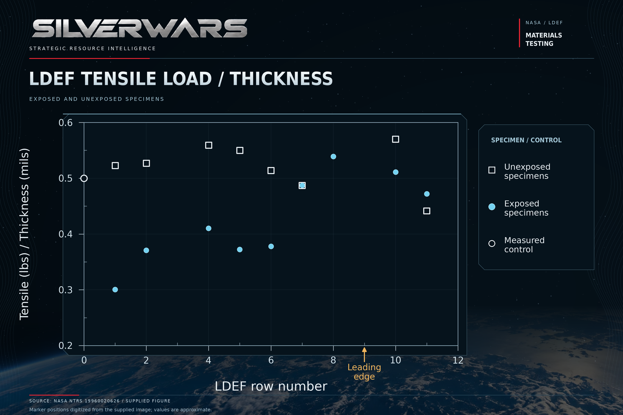
The same flight left a different result in the mechanical tests. On surfaces exposed to solar ultraviolet radiation without substantial direct atomic-oxygen exposure, the polymer's strength had fallen by about 30% relative to unexposed specimens. Its ability to stretch before breaking had declined too. The surface could still handle incoming sunlight and outgoing thermal radiation much as it had before launch, even though its film could tolerate less stretching.
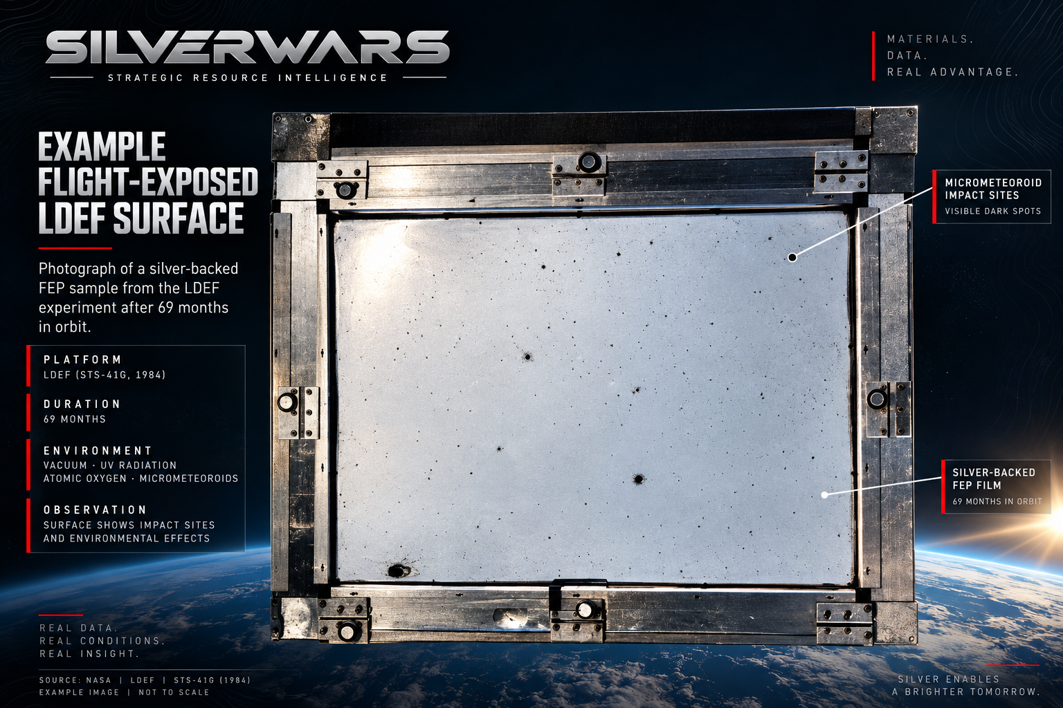
For a spacecraft builder, the important question is what the installation asks that aged film to do. LDEF's main blankets generally stayed intact. Adhesive-backed fastening tape on other experiment modules tore extensively. NASA's returned-material analysis traces both outcomes through the material's exposure and the loads it carried.
A mirror thinner than the material protecting it
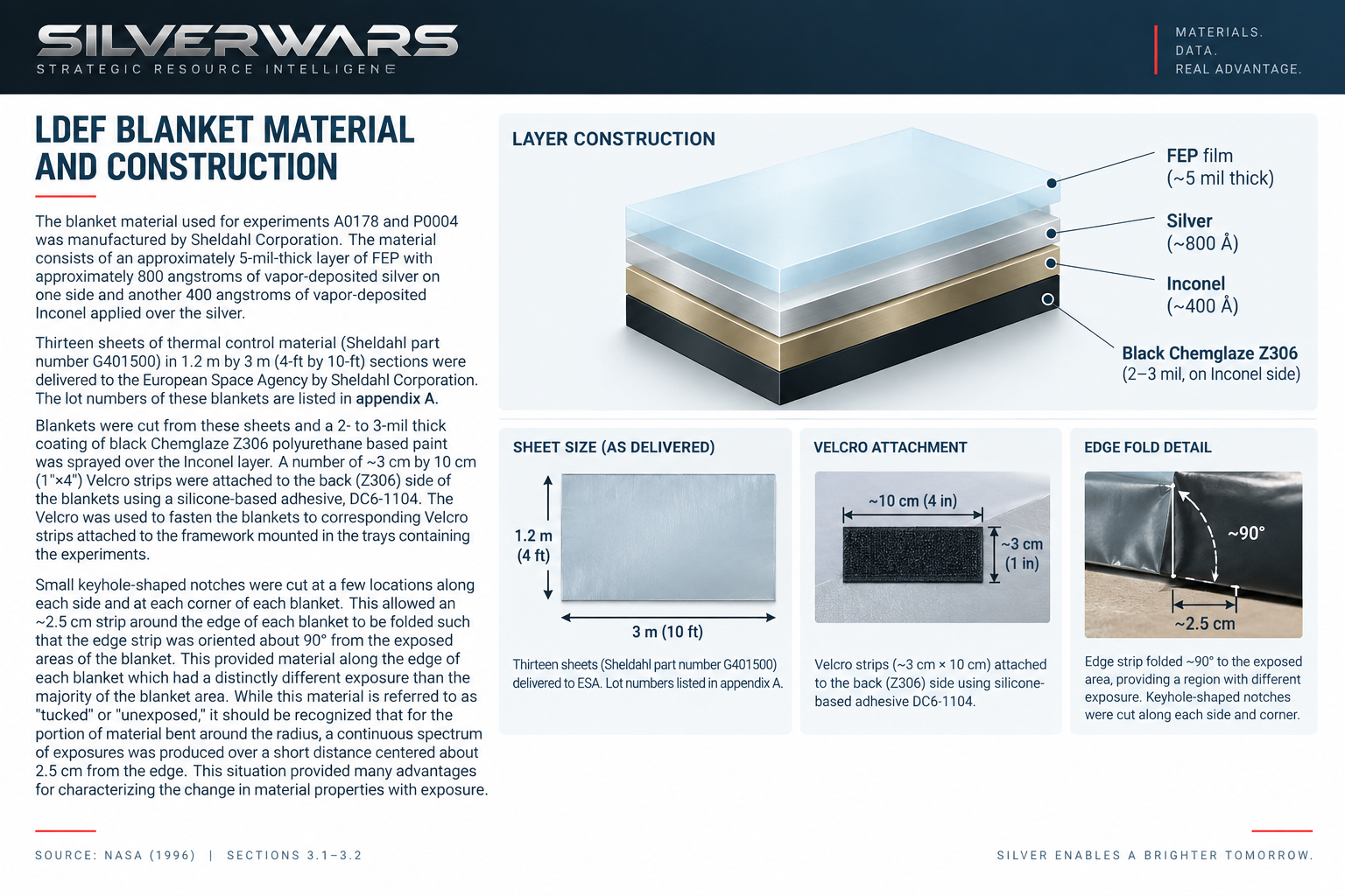
The main blanket construction described in NASA's report used a sheet of fluorinated ethylene propylene, or FEP, about 127 micrometres thick. Behind it sat approximately 80 nanometres of vapor-deposited silver, followed by an Inconel backing layer. Paint, adhesive and fastening strips completed the installation. Those dimensions describe that historical construction; they are not a specification for every silverized film.
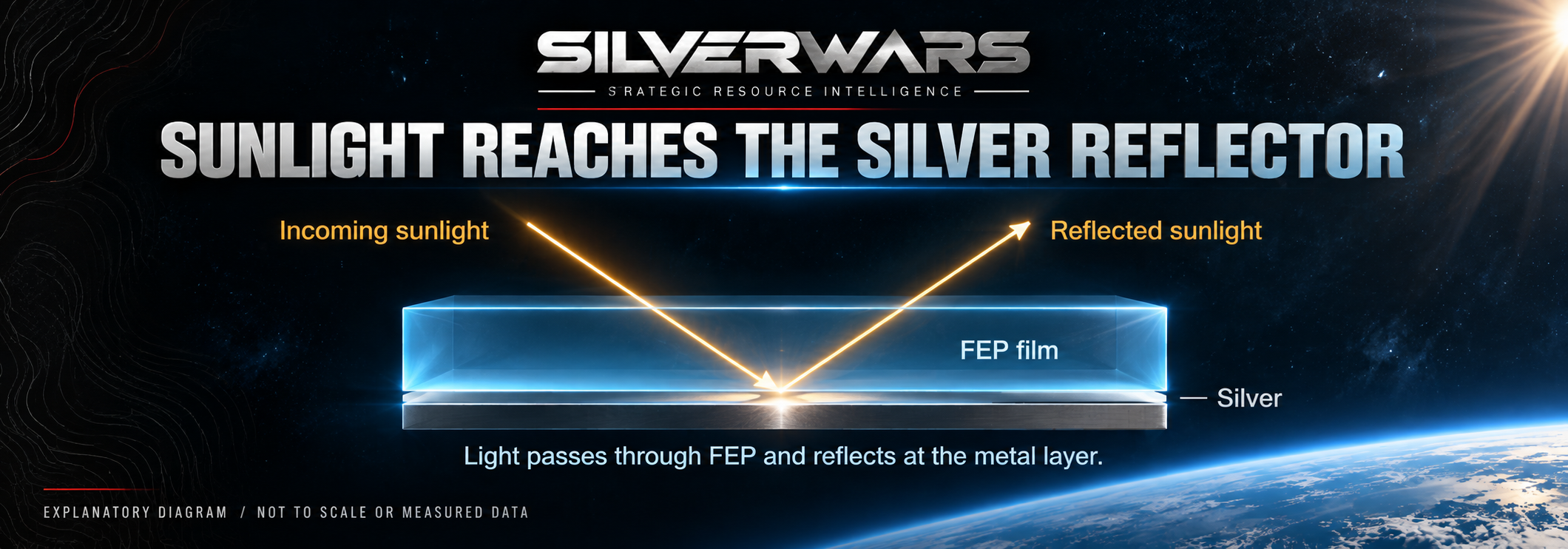
Silver's contribution was optical. Sunlight could pass through the visibly transparent FEP, reach the much thinner metal layer and be reflected outward, limiting the solar energy absorbed by the surface.
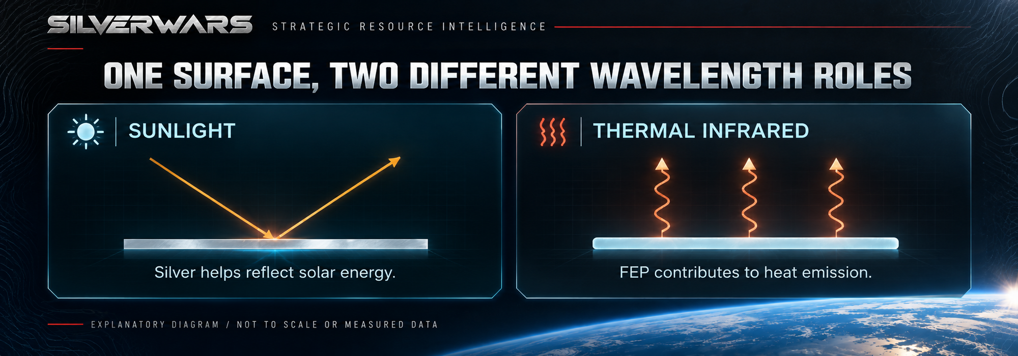
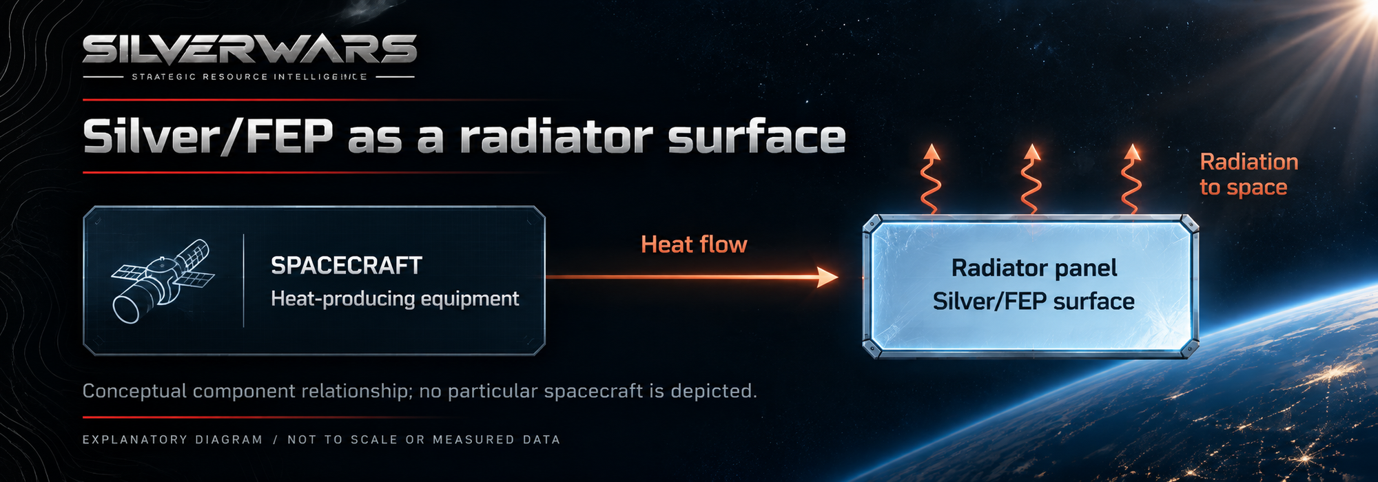
FEP did another job at longer wavelengths. A material that transmits much of the incoming sunlight can still emit thermal infrared radiation effectively. The stack combined low solar absorption with useful heat emission. On a radiator, that combination helps reject spacecraft heat while limiting added solar heating. Used as the outer face of an insulation blanket, it helps control the blanket's exchange with its surroundings; the underlying insulation performs a separate function.
NASA's current thermal-control guide still includes silver/FEP among its radiator coatings. LDEF gives this material family an unusually detailed flight record because the spacecraft returned with several different exposure histories still laid out across its exterior.
 Taylor Cross
One spacecraft, different kinds of deterioration
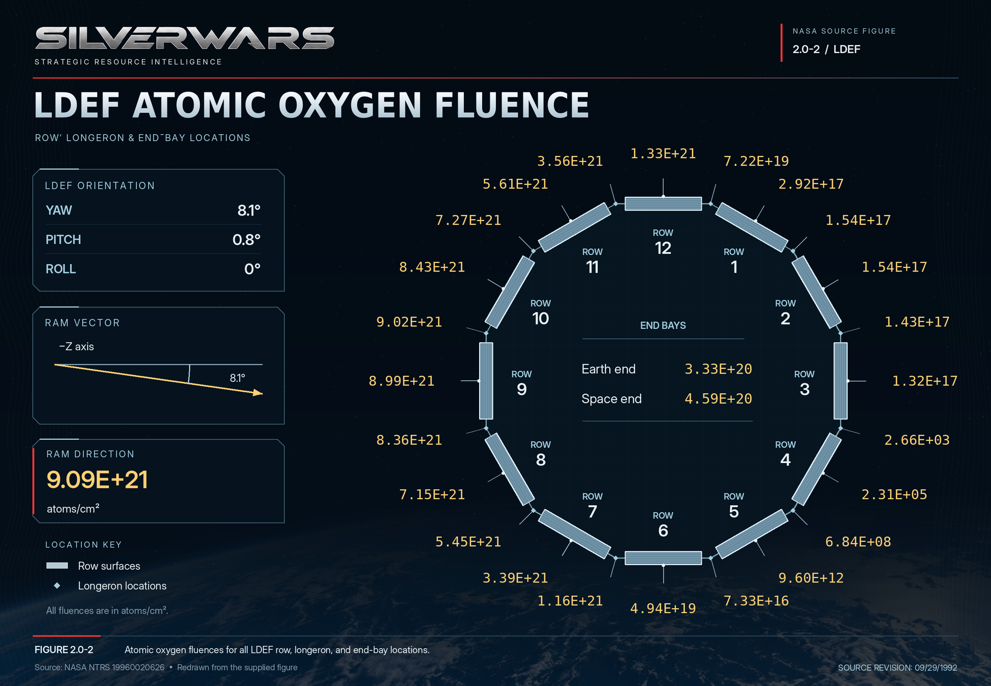
LDEF kept a fixed orientation relative to its direction of travel. Its forward-facing surfaces encountered substantial atomic oxygen as well as solar ultraviolet radiation. Trailing surfaces received solar exposure with far less direct atomic oxygen. The spacecraft completed 32,422 orbits before retrieval.
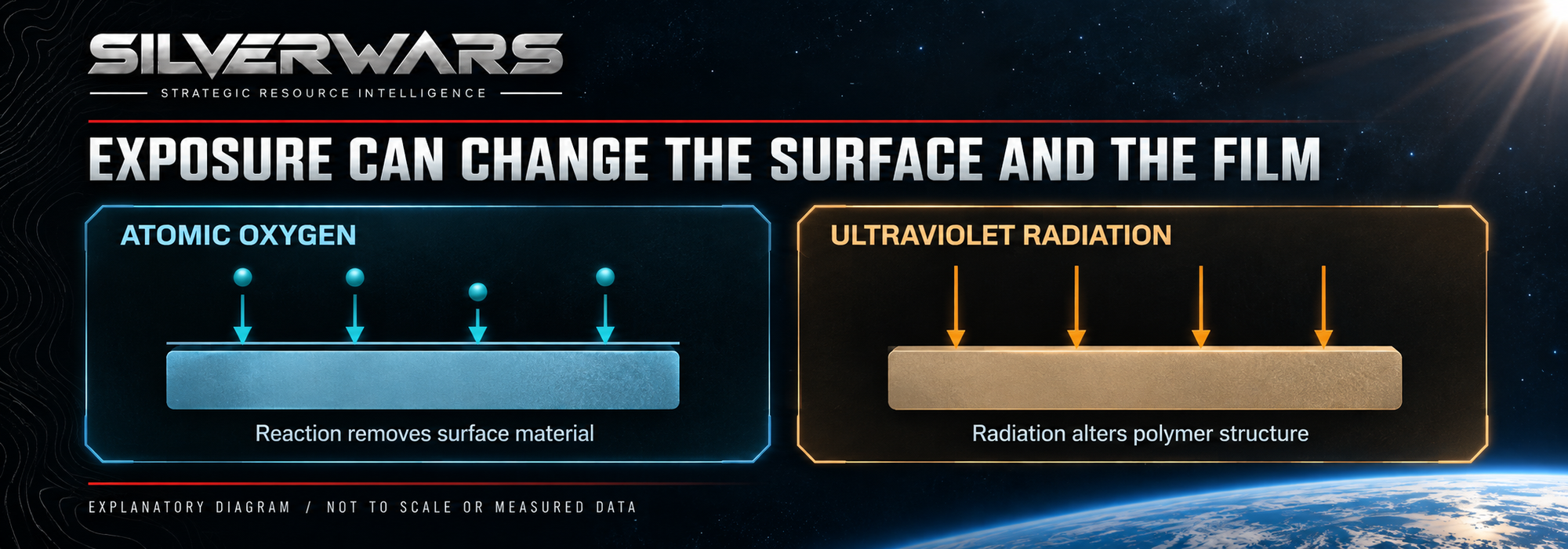
Atomic oxygen is chemically reactive oxygen present in the thin atmosphere of low Earth orbit. Reactions at a polymer surface can produce volatile material that escapes, gradually removing the surface. Solar ultraviolet radiation can also alter the polymer's molecular structure.
On LDEF's ultraviolet-exposed trailing surfaces, FEP became less strong and less able to stretch. Forward-facing material lost thickness and developed a rougher texture under combined exposure, yet showed a smaller change in measured tensile properties. Researchers interpreted that pattern as ultraviolet damage extending into the film while atomic oxygen removed altered material at the surface. Their report left parts of the combined mechanism unresolved.
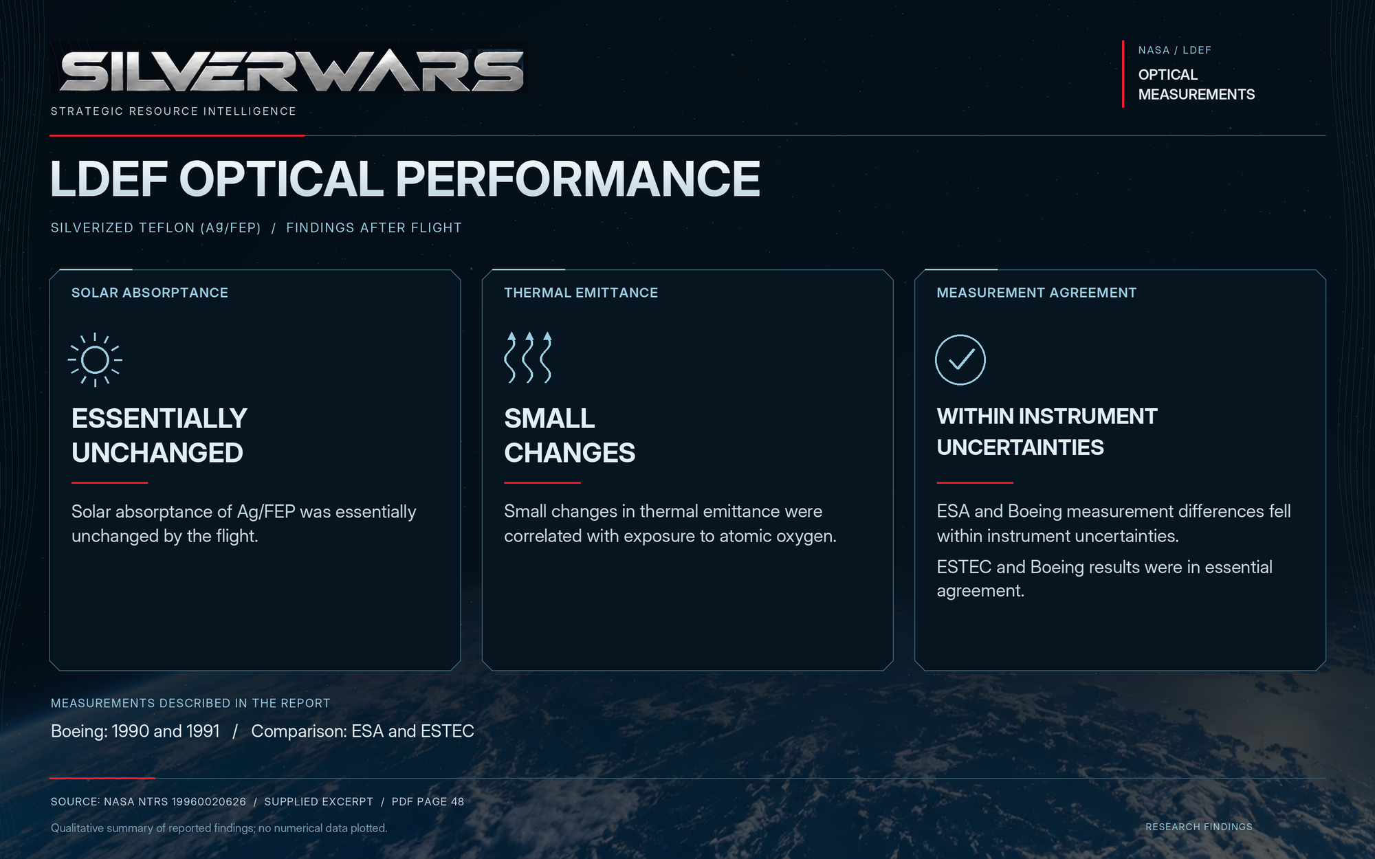
The optical results remained encouraging. Solar absorptance was generally little changed, and emittance changed only slightly in some exposed specimens. The survey deliberately sampled intact areas away from large visible impacts, so it describes surviving material rather than every damaged patch. Within that scope, the silver/FEP system had performed well through nearly six years in orbit.
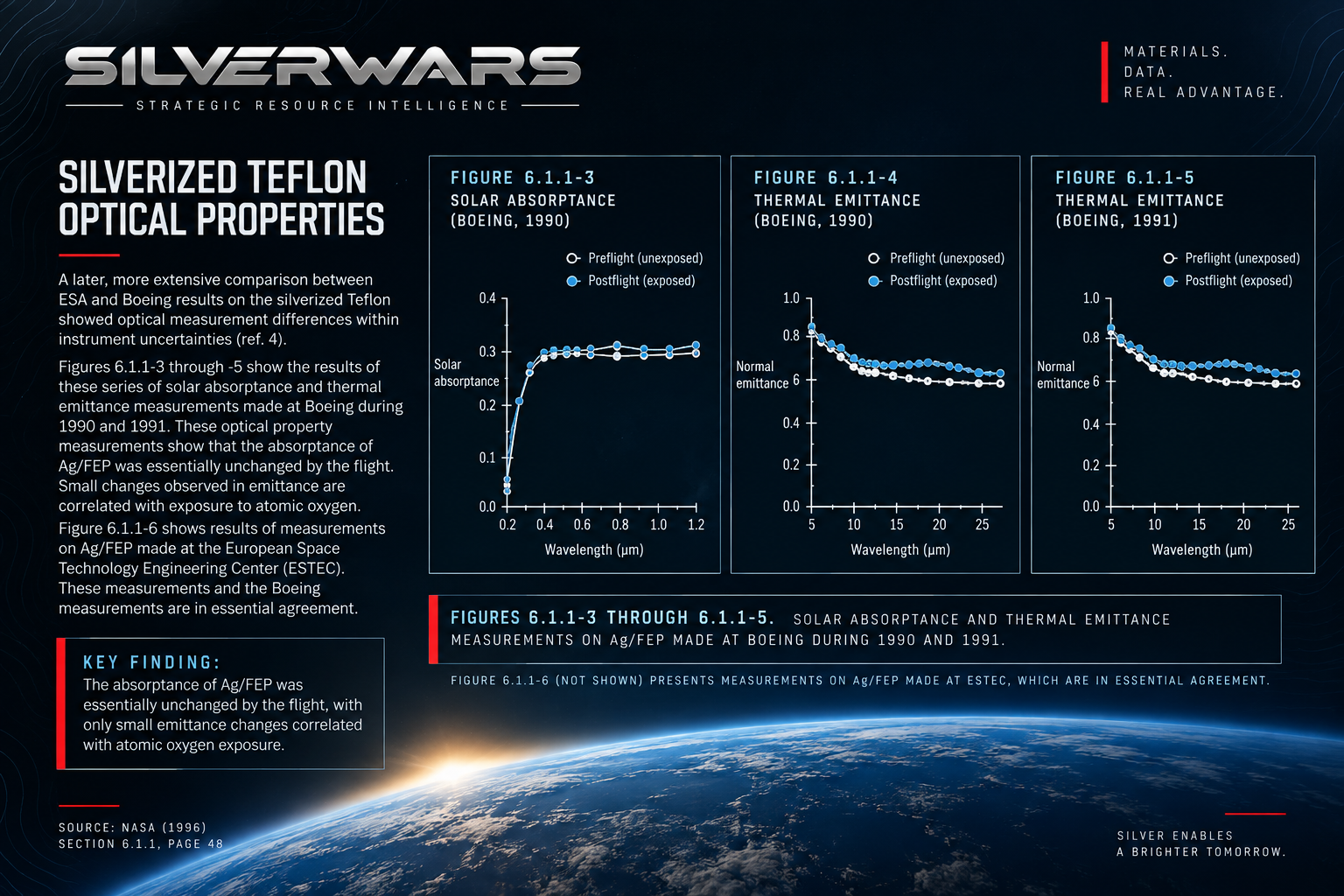
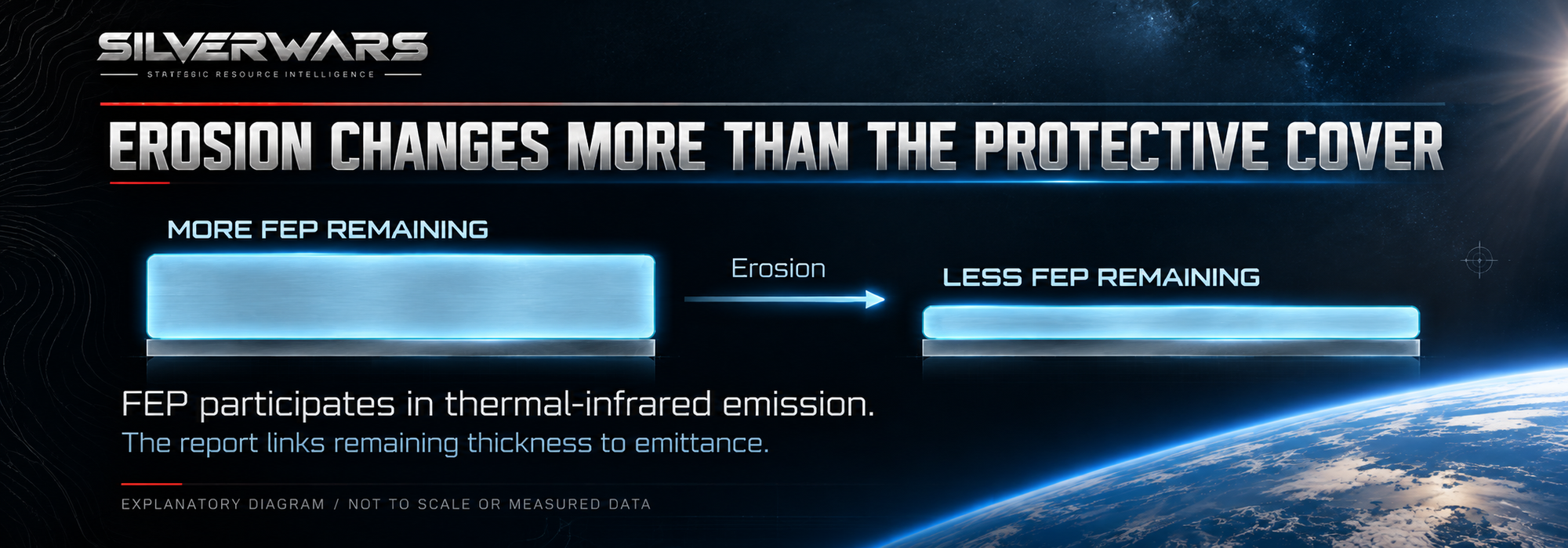
Thinning nevertheless had a route back into thermal performance. The report found that FEP's emittance decreased as the film became thinner, with a stronger change at small remaining thicknesses. FEP was doing more than covering the silver: it was part of the radiating surface. Removing it could reduce heat emission even while the metal beneath remained reflective.
The blankets held; some fastening tape tore
The principal LDEF blankets generally maintained their mechanical integrity, including at their attachment points. Adhesive-backed silverized FEP fastening tape on the M0001 experiment modules had a less successful history. It tore extensively and separated along at least two sides of every module.
NASA's report identified thermally induced stress as the likely cause of that tape failure, with solar damage to the material a possible contributor.
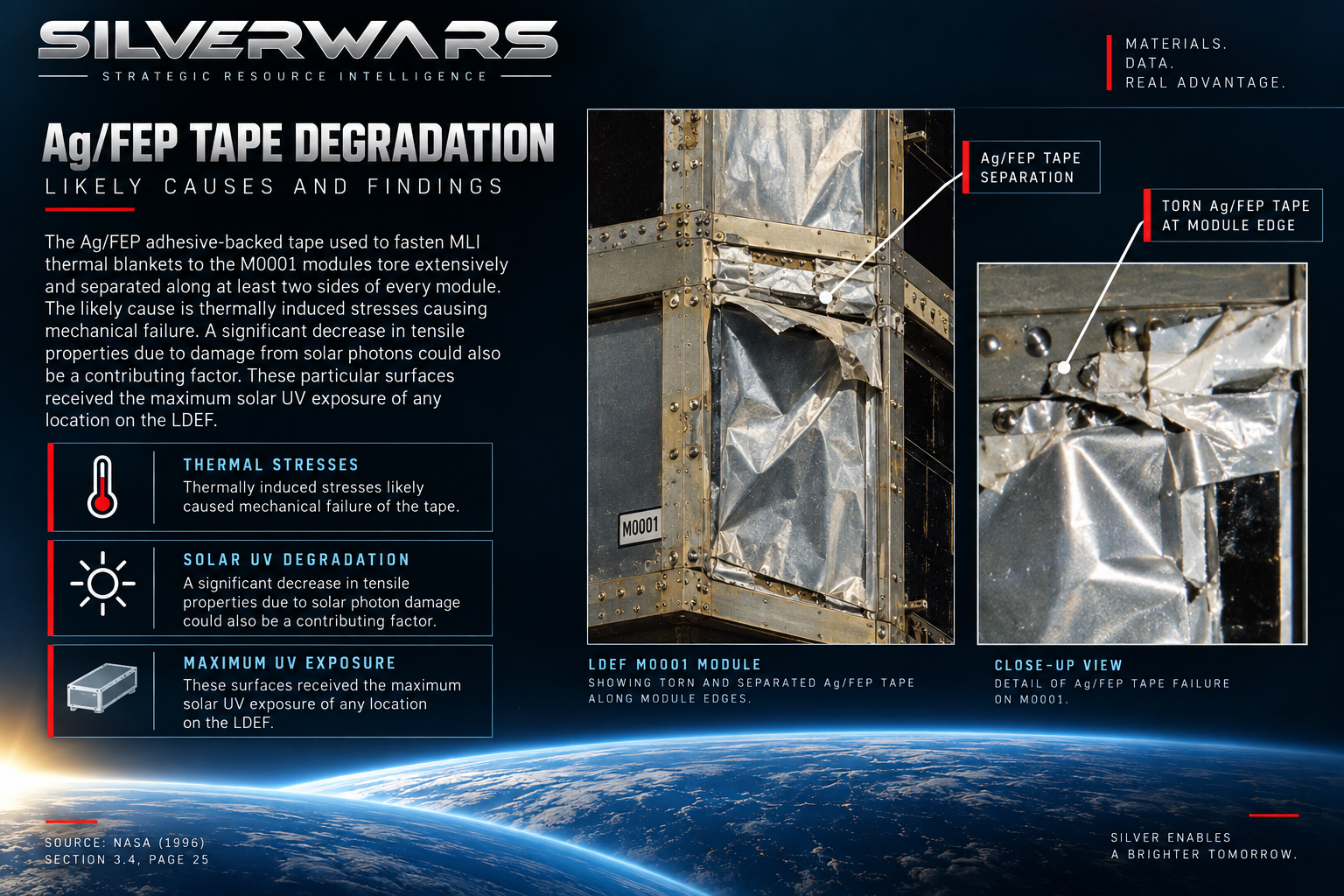
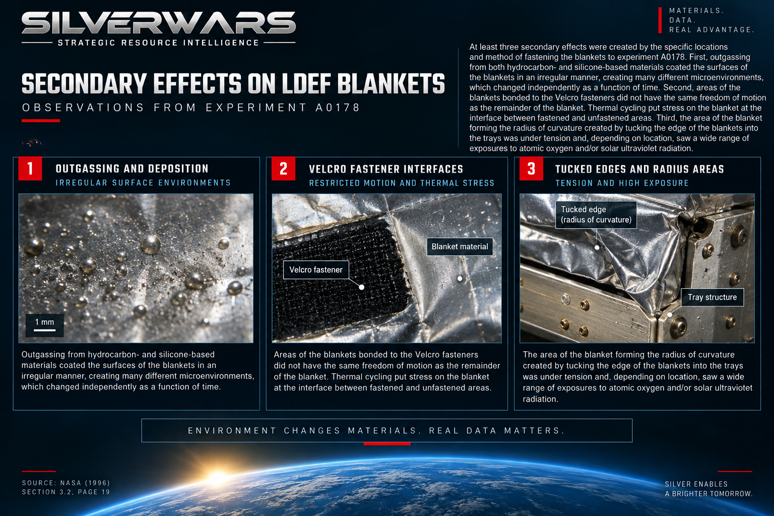
The blanket installations contained transitions between restrained and free material. Fasteners held one region while neighboring film could move as temperatures changed. The report's discussion of blanket-edge stress describes tension where material was stretched around a radius. Folded edges also exposed neighboring areas at different angles. Across a short distance, the same sheet could encounter a different load and a different environment.
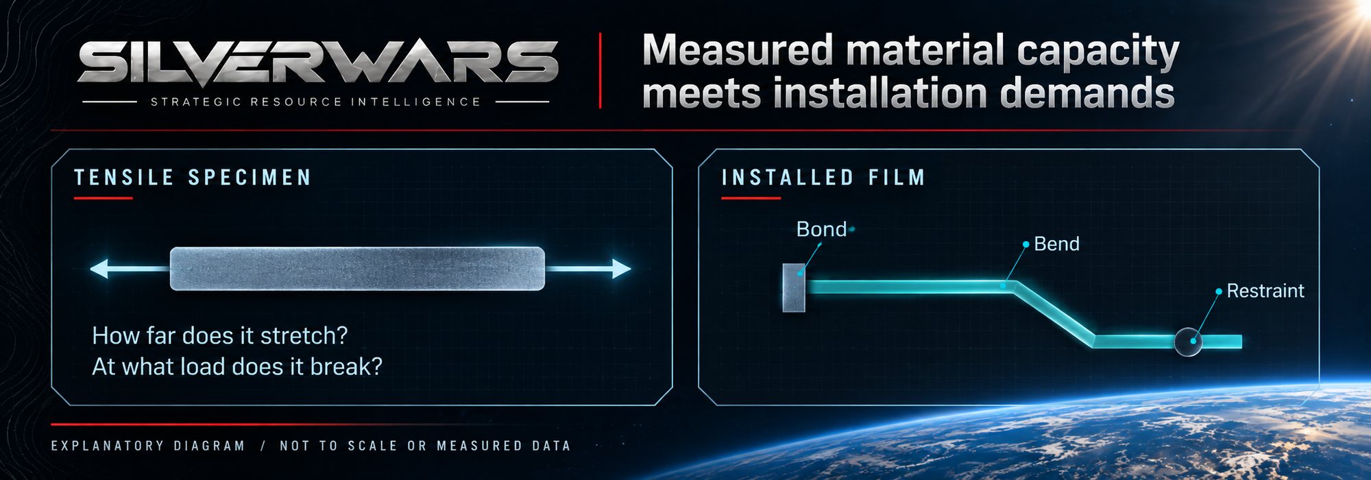
A tensile test measures how a specimen stretches under load and when it breaks. Bends, bonds and restraints help determine the loads and movement it must accommodate in an assembly. Once an exposed film has lost some ability to stretch, those installation details become central to interpreting its remaining usefulness.
Hubble's two faces aged differently
A later NASA study of Hubble insulation examined silver/FEP material removed from a solar-array drive arm after 8.25 years in space. Its sunward face contained cracks through the film's thickness. Measured tensile strength there was about 60% lower than on the anti-solar face of the same returned assembly.
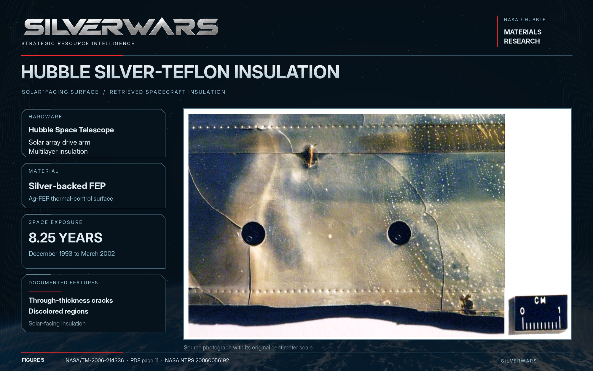
Both sides in that strength comparison had flown in space. A separate comparison with pristine FEP found roughly 90% lower elongation on the solar-facing side, while anti-solar material retained similar ductility to pristine film. Two parts of one installation returned with very different remaining ability to stretch.
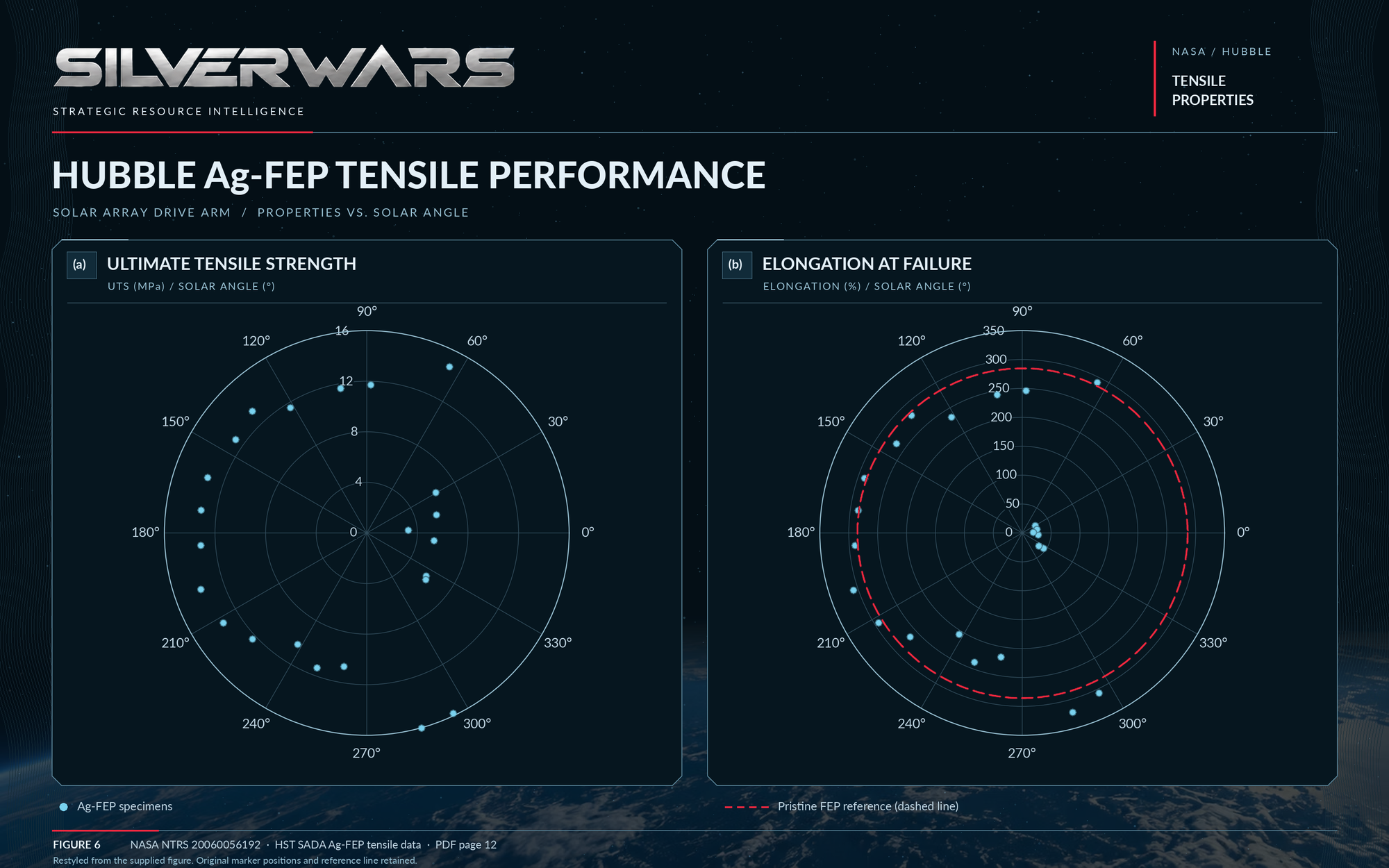
Hubble's construction, exposure and thermal history differed from LDEF's, so the two flights cannot set an expiration date for another spacecraft. They do make the local history consequential. A count of years in orbit leaves out which face received sunlight and how its aged film was held in place.

What the spacecraft can still count on
LDEF supplies a substantial positive result: particular silver/FEP surfaces kept their useful optical behavior through nearly six years in orbit. A spacecraft builder comparing that record with a new design has two connected questions: how its construction and exposure differ, and how the installation will keep the useful surface in place.
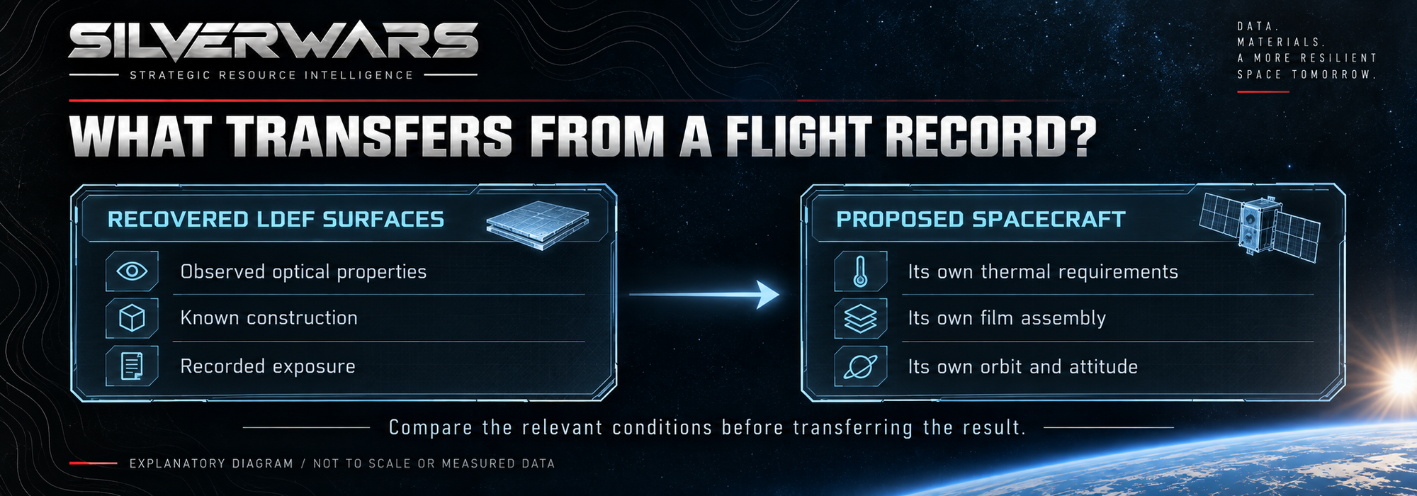
Durability testing can bring those questions into the same assembly. Aged film with representative bonds, bends and restraints must accommodate the expected loads and movement. Its optical properties must also meet the thermal requirements. Testing both can challenge the useful surface area and service duration assumed in the design. A successful flat specimen alone cannot answer how a restrained edge will behave.

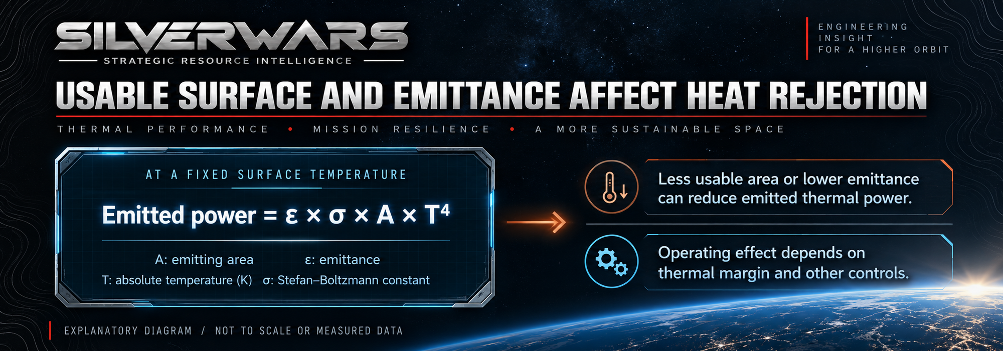
A payload or onboard processor keeps producing heat late in a mission. Losing useful emitting area or reducing emittance can leave less heat rejection available at a given temperature. Remaining margin and other temperature-control measures may accommodate it; otherwise equipment operation may need to be limited.
A thicker film, different support or revised attachment brings its own mass, flexibility and integration tradeoffs. The flight evidence gives a reason to examine those choices while the design is still movable. Silver had done its reflective job. The remaining question was how much the FEP covering the silver could endure while keeping that useful surface in place.