Silver
—
USD / troy oz
—
Connecting to provider
 Strategic Resource Intelligence

NINE SERVICE DEPOTS / LOW EARTH ORBIT
Nine depots. One serviceable constellation.
Run a mission, test the engineering, or explore the build plan.
ENNEAD / NINE-DEPOT ARCHITECTURE
9 depots · 225 active · 18 reserves · 243 clients total
2–48 satellites, including reserves. Applies equally to all nine depot clusters.
Part of the cluster total. Automatically limited to leave at least two active satellites.
25 active + 2 reserves per cluster · 225 active + 18 reserves network-wide.
One cluster per depot, spread around its assigned orbital plane. Nine depots is the chosen design premise. Placement, parking orbits, capacity and handoff timing still need optimization.
Choose the client before opening. In cluster mode it marks the center of the opening. Restore slots before changing the plan.
Illustrative spacing changes affect only the selected hub’s orbital plane. Real ISS or launch-vehicle clearances require tracking, trajectory analysis and operator coordination; this model does not establish a safe passage.
02 / QUESTION THE ASSUMPTIONS
Start with one local service route. Then count all nine depots in the network’s mass budget, with an equal number of spacecraft assigned to each.
A traffic maneuver is paused. Return to Mission control and restore normal slots to change orbit or fleet settings.
Electric mode gives a propellant equivalent for the ideal Δv. A real low-thrust transfer needs a different trajectory and time model.
Velocity change to reach the depot and return.
Changing planes can cost far more than changing altitude. Assign depots to compatible orbital planes.
Calculated: circular orbits, Earth two-body gravity, coplanar impulsive Hohmann transfer. Excludes phasing, docking, plane drift, drag during transfer and reserves. Coast time is not total service time. Transfer propellant uses the selected dry mass; the fleet study adds its configured service hardware. Station-keeping demand is an input, not calculated from altitude. The animation above is a separate schematic.
TARGET ACTIVE ROSTER / GEOMETRIC VISIBILITY
Test nine evenly spaced, truly polar orbital planes with evenly spaced active satellites in each. This tests the target roster after any reserve handoff. “Coverage” here means at least one satellite is above the minimum viewing angle, everywhere at all times, under this ideal geometry.
Uses the operating altitude above and active cluster roster; reserve satellites are excluded from the visibility calculation. Lower viewing angles give a larger footprint but longer, more obstructed signal paths. Satellites must be distributed around their orbital tracks.
Footprint half-angle: ψ = acos[R/(R+h) × cos(e)] − e. R = 6,371 km; h is altitude; e is minimum ground elevation. For P equally spaced polar planes and S satellites per plane, every ground point is within acos[cos(90°/P) × cos(180°/S)] of a satellite. A footprint below 90°/P necessarily leaves equatorial gaps. Between these bounds, phasing analysis is needed.
Traffic repositioning changes the spacing used by this bound. The result shown describes the nominal uniform roster, not coverage during an open traffic window.
All modeled active clients must be available and evenly spaced. Reserve handoffs are assumed to preserve that spacing; timing and failure resilience are not modeled. This does not establish radio link margin, traffic capacity, imaging access, collision safety or continuity during servicing. The network animation is a schematic, not this exact polar geometry.
ILLUSTRATIVE LOGISTICS / NO COST CLAIM
Charge all nine depots, their tanker allowances and every active or reserve client to the fleet. Compare with replacing propellant-limited spacecraft, or carrying more fuel from launch. 27 satellites per cluster is the starting roster. Adjust cluster size and reserves above the simulation to update this study.
Adjust cluster size & reserves ↑*Optimistic reference: extra tank structure is not included.
Loading scenario…
Includes client service hardware, ideal client transfer maneuvers and the full dry mass of all nine depots and their tanker allowances. Excludes depot station keeping, tanker propulsion, disposal reserves, launch upper stages, delivery packaging, extra coverage spares, unexpected failures and real multi-plane placement and scheduling. This is payload mass accounting—not launch count, environmental impact, profitability or a validated lifecycle forecast.
03 / FROM CONCEPT TO FLIGHT
This is an invitation to investigate a serviceable constellation supported by nine depots. The components have precedent. The integrated system must demonstrate timely handoffs, enough reserve capacity and a dependable mineral-to-component supply chain.
Specify the materials and components. Give the client a cooperative navigation target, a standardized capture interface, a compatible propellant connection and modules a robot can reach.
Fly one depot and one purpose-built client. Demonstrate repeated rendezvous, measured propellant transfer, safe separation and a return to useful operation.
Add a second client and a replaceable module. Measure performance, qualify supply capacity, then validate the deployment plan for nine depots across compatible service planes.
NEXT STEPS / FROM MATERIALS TO MISSION
Build the supply plan alongside the spacecraft. Establish what the fleet needs, where materials are refined, and who can manufacture qualified flight components.
Audit silver and copper use in electrical and power hardware with component suppliers. Extend the inventory to structural metals, solar-cell materials, battery chemistry and propulsion consumables as the design takes shape.
Initial fleet: 243 satellites, including 18 reserves, plus 9 depots. Add support vehicles, manufacturing losses and 15 years of replenishment to the procurement plan.
Planning roadmap: mineral quantities, suppliers and supply agreements have not been established. The mass calculator does not estimate mineral content.
Create a component-level bill of materials for satellites, depots and support vehicles. Specify mass, purity and grade; include prototypes, manufacturing losses, reserves, replacement modules and propulsion consumables.
DELIVERABLE A verified materials register and demand forecast.
Trace priority materials from mines or recyclers through refining, fabrication and component manufacturing. Check processing bottlenecks, geographic exposure and lead times; two vendors may share the same upstream source.
DELIVERABLE A supplier map showing common dependencies.
Develop independent supply routes with documented provenance. Test materials and components for the mission environment. Negotiate phased supply or offtake agreements tied to specifications, qualification milestones and verified capacity.
DELIVERABLE Qualified sources and a staged procurement plan.
Size material and component inventories against consumption, delivery times, disruption scenarios and shelf life. Include service modules and propulsion consumables, then update the plan as cluster size and mission duration change.
DELIVERABLE An inventory and replenishment policy.
Design replaceable modules and measure the materials retained through longer service life. Recover manufacturing scrap on Earth. Evaluate orbital salvage, return and recycling as separate capabilities that need demonstration.
DELIVERABLE A lifecycle material balance, including servicing infrastructure.
A materials register, supplier-risk map and qualification plan for one demonstrator, followed by a demand forecast for the full nine-depot network.
Nine service depots. A fleet built for renewal.
Shared standards, local service routes, and replenishment from Earth.
ORBITAL MAINTENANCE / RESPONSIBLE OPERATIONS
A serviceable constellation needs a serviceable operating environment. Prevent new debris, address existing hazards and assess recoverable objects as potential sources of useful components and materials.
Plan orbital maintenance alongside the depots, client fleet and mineral supply. Recovery operations must protect working spacecraft and account for the equipment needed to perform the work.
Proposed ENNEAD planning scope. This demonstrator does not model existing debris, collision avoidance or capture. Capture success, return vehicles, recovery and maintenance masses, and usable material yields remain unspecified.
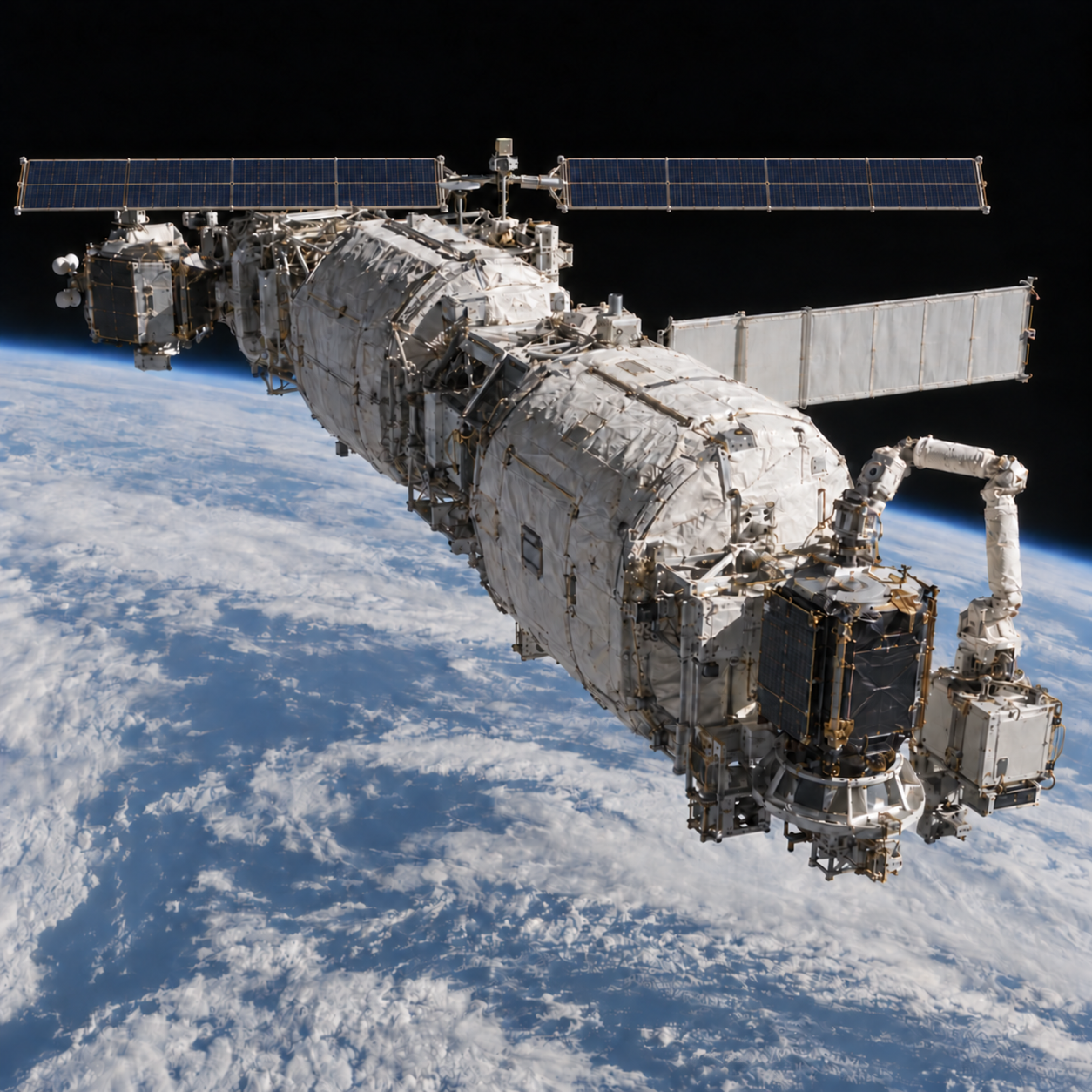
Monitor close approaches, plan avoidance maneuvers and coordinate servicing traffic. Secure tools and detached parts during every operation. Give clients, depots and support vehicles a disposal plan that still works after foreseeable failures.
DELIVERABLE A collision-avoidance and debris-prevention operating plan.
Establish each target’s orbit, rotation, condition and possible attachment points. Prioritize reachable objects whose removal would reduce risk. Account for uncooperative, tumbling targets and hardware never designed to be captured.
DELIVERABLE An inspected target list with mission limits and removal priorities.
Match the target’s motion, establish a secure hold and control the combined assembly before towing. Define abort and failed-capture procedures. Keep uncertain or damaged objects away from active depot berths until inspection establishes safe handling.
DELIVERABLE A demonstrated capture sequence and an isolated recovery work area.
Compare repair, direct component reuse and material processing in orbit. Composition, contamination, damage and processing effort determine what can be used. Keep captured mass separate from qualified parts and measured material yield.
DELIVERABLE A recovery assessment with verified uses, yields and rejected material.
Evaluate each as a separate flight mission. Intact Earth return needs containment, a qualified entry vehicle, thermal protection, a descent system such as parachutes, and ground recovery. Controlled disposal needs its own trajectory and safety assessment.
DELIVERABLE A qualified destination and a complete return or disposal plan.
Inspect capture arms, tools, docking hardware, propellant connections, power and thermal systems. Carry replacement modules and replenishment supplies. Plan maintenance downtime and the rescue, repair or safe disposal of a failed servicer or depot.
DELIVERABLE A maintenance, spares and failed-vehicle recovery plan.
ESA is developing active debris removal. NASA documents servicing experience and emerging orbital recycling capabilities. Stardust demonstrated protected sample return to Earth. These precedents support investigation; ENNEAD debris recovery, material reuse and depot maintenance still require their own demonstrations.
05 / TAKE THE STUDY FORWARD
Take your current scenario into the next discussion. Review the precedents and the questions still open.
EXPLORE. CHALLENGE. DEVELOP.
Download the brief and your current assumptions. Use the model as a starting point for a real engineering study.
DARPA’s Orbital Express tested autonomous satellite servicing in orbit. NASA describes fleets of servicers operating from fuel depots. Electric propulsion has counteracted atmospheric drag on missions such as GOCE.
These precedents do not establish the performance or economics of ENNEAD.
Model v0.2. μ = 398,600.4418 km³/s²; Earth radius = 6,371 km; g₀ = 9.80665 m/s². Hohmann transfers use vis-viva; propellant uses the ideal rocket equation. This demo is an architectural concept and educational calculator, not a flight dynamics simulator, collision assessment or investment forecast. No patent clearance or novelty claim is implied.
Inspect the calculation source ↓