
For a copper investor, the first useful question is not how many drones will fly. It is what the motor actually asks copper to do, and the answer is more interesting than "conduct electricity."
The ESC converts battery DC into controlled motor-phase currents. The motor converts electrical power into shaft torque and rotational power, and the propeller converts that rotational power into aerodynamic thrust. The propulsion system has to support the aircraft, including the motor's own mass. Mixing those steps sounds harmless, but it encourages a bad mental model in which copper somehow creates lift by merely being present.
The Copper Stays Still While the Rotor Moves
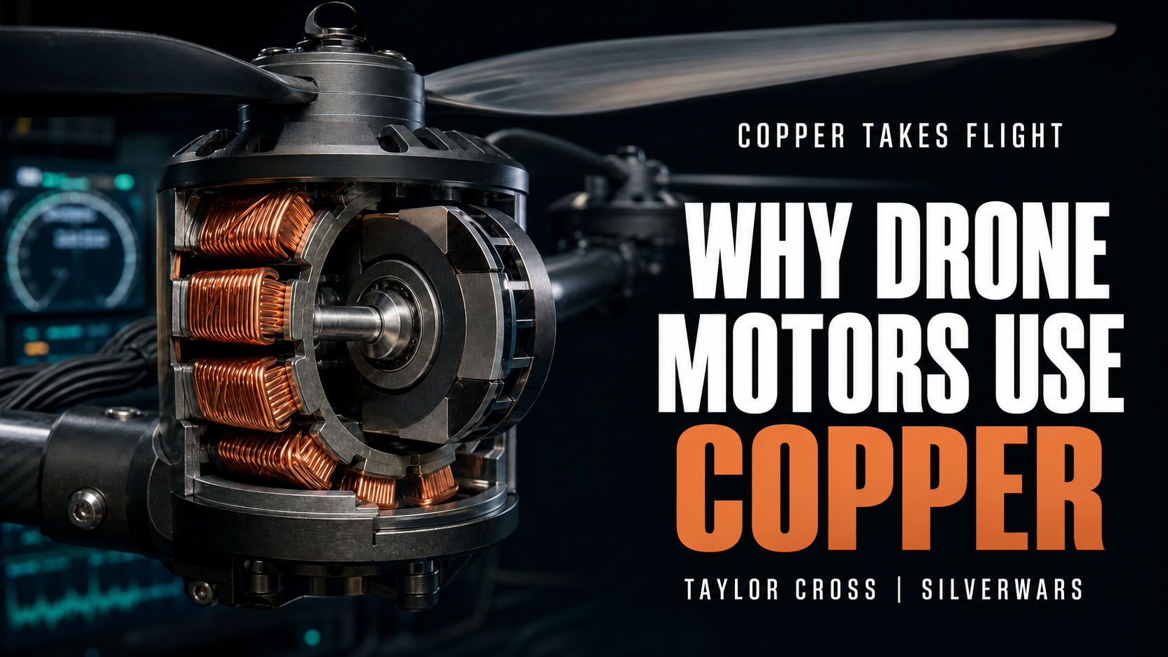
DJI's explanation of its brushless motors is a useful place to see the basic arrangement. In the motors described there, insulated copper coils sit on a fixed stator. Permanent magnets sit in the surrounding rotor. Change the current through the stator windings in the right sequence and the electromagnetic field pulls the rotor around.
That is one common permanent-magnet outrunner construction, not the only motor architecture in aviation. NASA's aircraft permanent-magnet machine design guide illustrates an inner-rotor geometry instead. A 2021 multirotor study examined a switched-reluctance motor whose rotor did not require permanent magnets at all.
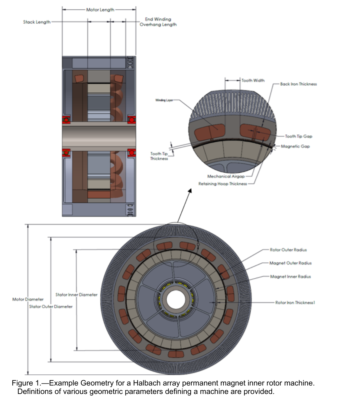
Both designs put controlled current through stator windings, but their torque mechanisms differ. In the permanent-magnet machine, stator current interacts with rotor-magnet flux. In the switched-reluctance machine, torque arises because winding flux linkage and inductance change with rotor position.
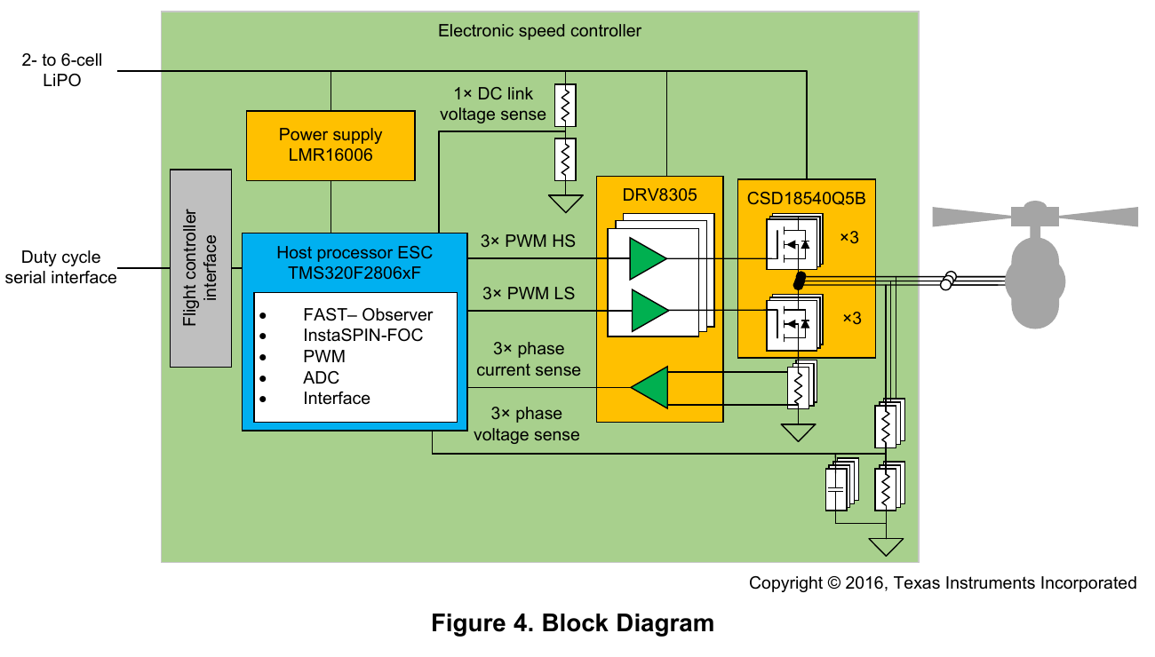
An electronic speed controller, or ESC, decides how that current arrives. Texas Instruments' TIDA-00916 drone ESC reference design uses three half-bridges, pulse-width modulation and rotor-position estimation to control three phase currents. TI tested its field-oriented control at up to 12,000 rpm with a six-pole-pair motor.
A 2024 outer-rotor multiphase permanent-magnet study makes the propulsion boundary explicit: the motor supplies shaft torque and power while the propeller produces thrust and pushes back with aerodynamic torque.
Winding Resistance Becomes a Flight Problem
Every meter of winding brings electrical resistance. Run current through it and some input power becomes heat according to the familiar current-squared relationship. NASA's motor-sizing guide builds winding loss from conductor resistivity, length, cross-sectional area, slot fill and temperature. Copper is attractive because its conductivity is high, but excellent conductivity is not zero resistance; as a winding heats and resistance rises, insulation, magnets, bearings and electronics are also moving toward temperature limits of their own.
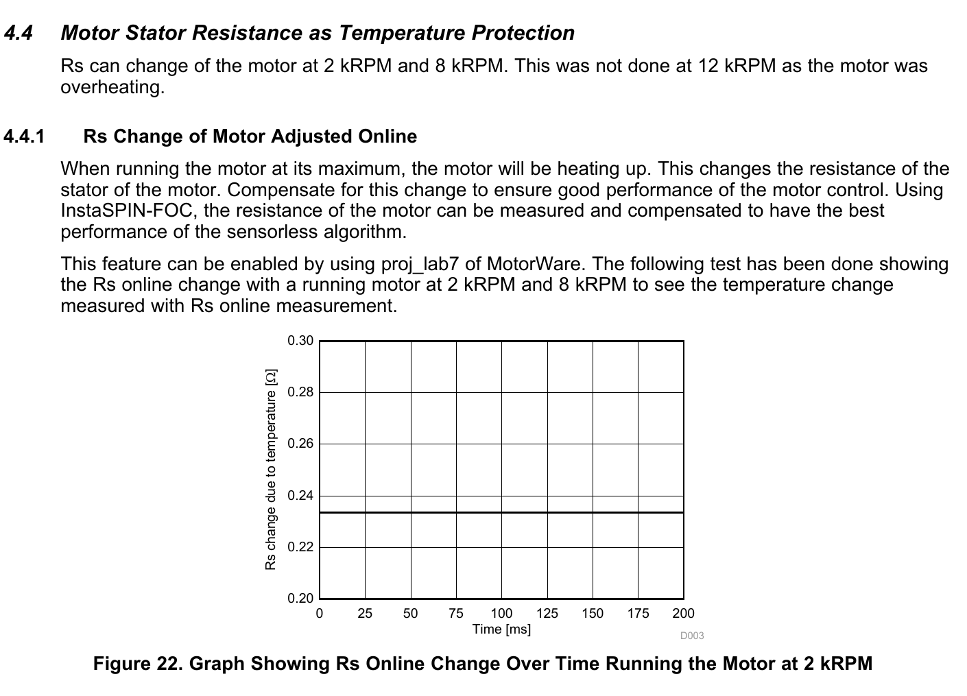
TI's reference design makes the feedback visible by estimating motor temperature from changes in stator resistance. In a test using a named Turnigy outrunner, resistance rose as the motor heated at 2,000 and 8,000 rpm; TI left the 12,000 rpm temperature run out because the motor overheated. That setup cannot provide a universal drone thermal curve, but it does show winding resistance changing enough to become part of the control problem.
There is no free thrust button labeled "more copper." Winding resistance belongs to a motor, inverter, propeller and cooling arrangement that has to work as one system.
Slot Fill Is a Geometry Decision, Not a Slogan
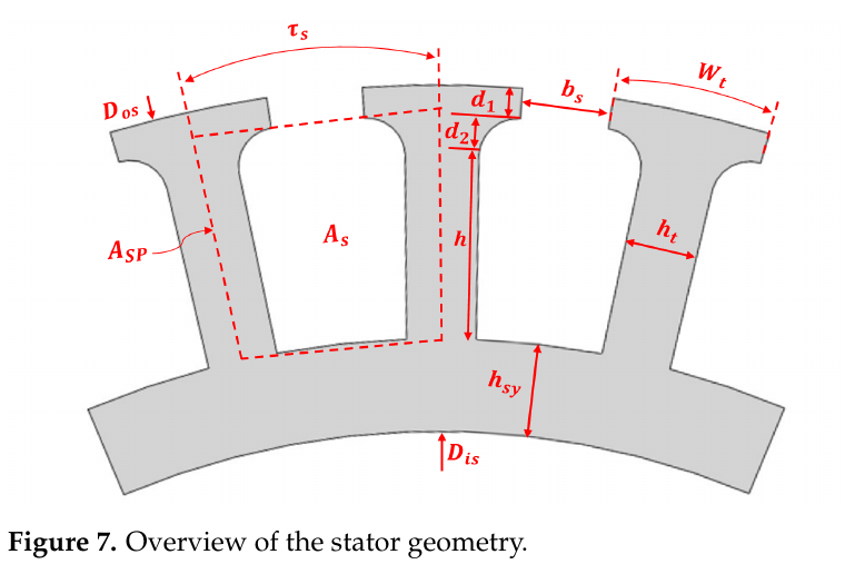
Motor designers do not have unlimited room for conductor. In the slotted-stator machines discussed here, conductor shares finite slot area with insulation and unavoidable gaps, which is why NASA cites 35% to 55% as a typical copper slot-fill range for round-conductor motors and uses 40% as an initial-sizing estimate. Other winding forms can pack more conductor, though the manufacturing and AC-loss questions change with them.
DJI says its winding machines improve uniformity and slot fill. That is first-party evidence about DJI's process. Its accompanying shorthand that more coils mean more power and efficiency should not be carried into an investment model. Changing turn count changes winding resistance and machine constants; the resulting voltage, speed, torque and thermal behavior depend on wire area, current, geometry and control. A higher fill factor can be useful, but a larger copper mass is not automatically a better motor.

GUNNISON COPPER (GCUMF) / PR
Release Routing Desk
Achieves Key Milestone Under U.S. Department of Energy 48C Program
One Motor Study Shows How Fast the Number Can Move
This is where copper intensity stops behaving like a simple commodity multiplier. A designer can shorten end turns, change wire area, alter turn count, raise voltage, reshape the magnetic circuit or select another topology. Each choice moves several constraints at once.
The only source in this set that reports winding-copper mass is also easy to misuse.
In "Designing Low-weight Switched Reluctance Motors for Electric Multirotor Propulsion System", the researchers report a 640-watt rated design parameter for an optimized switched-reluctance motor based on a 2D finite-element model for a 10-kilogram quadrotor target. Their original modeled motor used 42 winding turns. A revised geometry used 30 turns at the same fill factor.
The reported material trade moved in opposite directions:
| Modeled motor version | Winding turns | Reported iron mass | Reported copper mass | Iron plus copper |
|---|---|---|---|---|
| Original design | 42 | 208 g | 103 g | 311 g |
| Modified design | 30 | 271 g | 74 g | 345 g |
The final column is simple arithmetic from the reported iron and copper values, and it exposes the point better than a percentage: the design shed 29 grams of copper and added 63 grams of iron. On those two reported material categories, the modified motor became 34 grams heavier.
That is not a full motor-mass comparison because housing, shaft, bearings, insulation and other materials sit outside those two columns.
In this modeled comparison, less winding copper did not reduce the iron-plus-copper subtotal; more iron helped reshape the magnetic path while fewer turns changed the torque-speed behavior. The paper evaluates a nonstandard research motor, not the permanent-magnet BLDC motor in a typical camera drone. Its 74-gram and 103-gram figures are modeled per-motor values, not a market range.
Treating 74 and 103 grams as an industry range would erase the experiment's topology and modeled scope. A four-motor subtotal would still describe only the paper's planned demonstrator, not a measured aircraft copper bill of materials.
 Taylor Cross
The Motor Design Sets the Copper Requirement
Copper’s role becomes clear inside the motor. In the copper-wound designs examined here, its windings carry the controlled current that helps produce shaft torque. Their resistance, dimensions and temperature affect how the propulsion system performs. Copper is part of the engineering that makes flight possible.
That engineering also determines how much copper a motor needs. Wire thickness, winding turns, available space and cooling all interact. A manufacturer changing the motor’s geometry can change its copper requirement even when the aircraft is intended to perform the same job. A small inspection drone and a heavy agricultural aircraft therefore need to be understood through their own designs.
For investors, this makes the connection between manufacturing and material use worth following. Rising production of a particular copper-wound motor would increase the number of windings that must be made. Changes in copper content per motor, replacement demand and manufacturing recovery would then shape the effect on copper purchases. A fleet-growth headline captures only part of that picture.
The cited research explains the physical role well, but it does not supply a reliable copper-per-aircraft figure for a production class. Estimating the market contribution requires measured copper content and production volumes for matching configurations.
Copper already has a demanding job in these propulsion systems: carrying current within tight limits on weight, heat and space. As drone manufacturing expands, the designs reaching production will determine the scale of the copper requirement.
 Taylor Cross